Loading 3D model
Drag the model to turn it
01 Description
The WF-01 Weather Frame is a battery-powered e-paper display that shows current weather conditions and a three-day forecast. It wakes on a fixed interval, downloads one pre-rendered image over Wi-Fi, draws it and returns to deep sleep. Between updates the panel holds its image with no power, so the frame draws current only for the few seconds of each update.
All layout and rendering happens on a host computer on the same network. The frame receives a finished 1-bit bitmap and needs no firmware change when the screen design changes.
Features
- 4.26″ e-paper panel, 800 × 480 px, black and white, 219 ppi
- Readable in direct light; the image stays with no power
- ESP32-S3 controller with 2.4 GHz Wi-Fi
- 1500 mAh LiPo battery, charged over USB-C with the case closed
- Four months typical runtime at a 30-minute update interval
- In-line power switch, reachable through the side wall
- Keeps the last good image if the network or the host is unavailable
- Printed two-part case: 114 × 71 × 32 mm, about 60 g
Applications
Desk and wall weather display. The same hardware shows any 800 × 480 1-bit image: pictures, signs, calendars and dashboards. WF-01 is the first experience of E-Display, a general e-paper platform.
02 Wiring and pin assignment
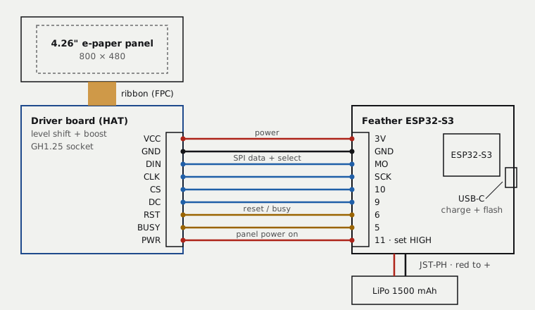
| Driver board | Controller pin | GPIO | Function |
|---|---|---|---|
| VCC | 3V | 3.3 V supply | |
| GND | GND | Ground | |
| DIN | MO | SPI data | |
| CLK | SCK | SPI clock | |
| CS | 10 | 10 | Chip select |
| DC | 9 | 9 | Data / command |
| RST | 6 | 6 | Reset |
| BUSY | 5 | 5 | Busy input |
| PWR | 11 | 11 | Panel power, driven high |
The driver board connects through a 9-pin GH1.25 cable (20 cm). The battery connects through the in-line switch cable to the controller's JST-PH socket.
03 Mechanical
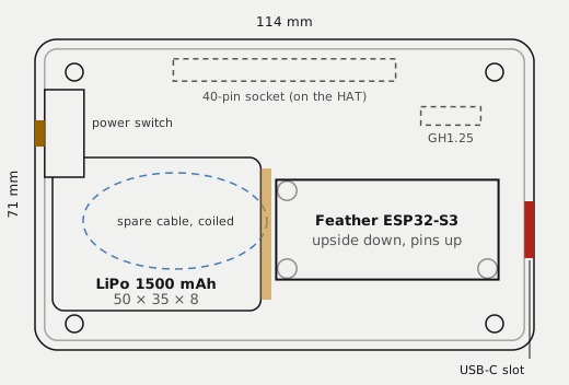
| Parameter | Value | Unit |
|---|---|---|
| Outline | 114 × 71 × 32 | mm |
| Corner radius | 5 | mm |
| Wall | 2.2 | mm |
| Edge chamfer | 0.8 | mm |
| Bezel depth / face | 6 / 2 | mm |
| Window | 95 × 58 | mm |
| Shell depth | 26 | mm |
| Mass | 60 typ. | g |
| Opening | Position | Size |
|---|---|---|
| USB-C charge slot | Right wall | 13 × 7 mm |
| Power button | Left wall | Ø 7.6 mm |
| RESET, BOOT | Back | Ø 1.8 mm pinholes |
| Keyhole | Back | Wall mount |
The case has two printed parts. The bezel holds the display board in a pocket, and four ribs press it flat. The shell carries the controller upside down on three standoffs and the battery on foam tape. The parts join with four snap tabs. Material: dark PETG or PLA for the bezel, clear PETG (prints frosted) for the shell. Both parts print without supports on a 180 mm printer.
04 Screen
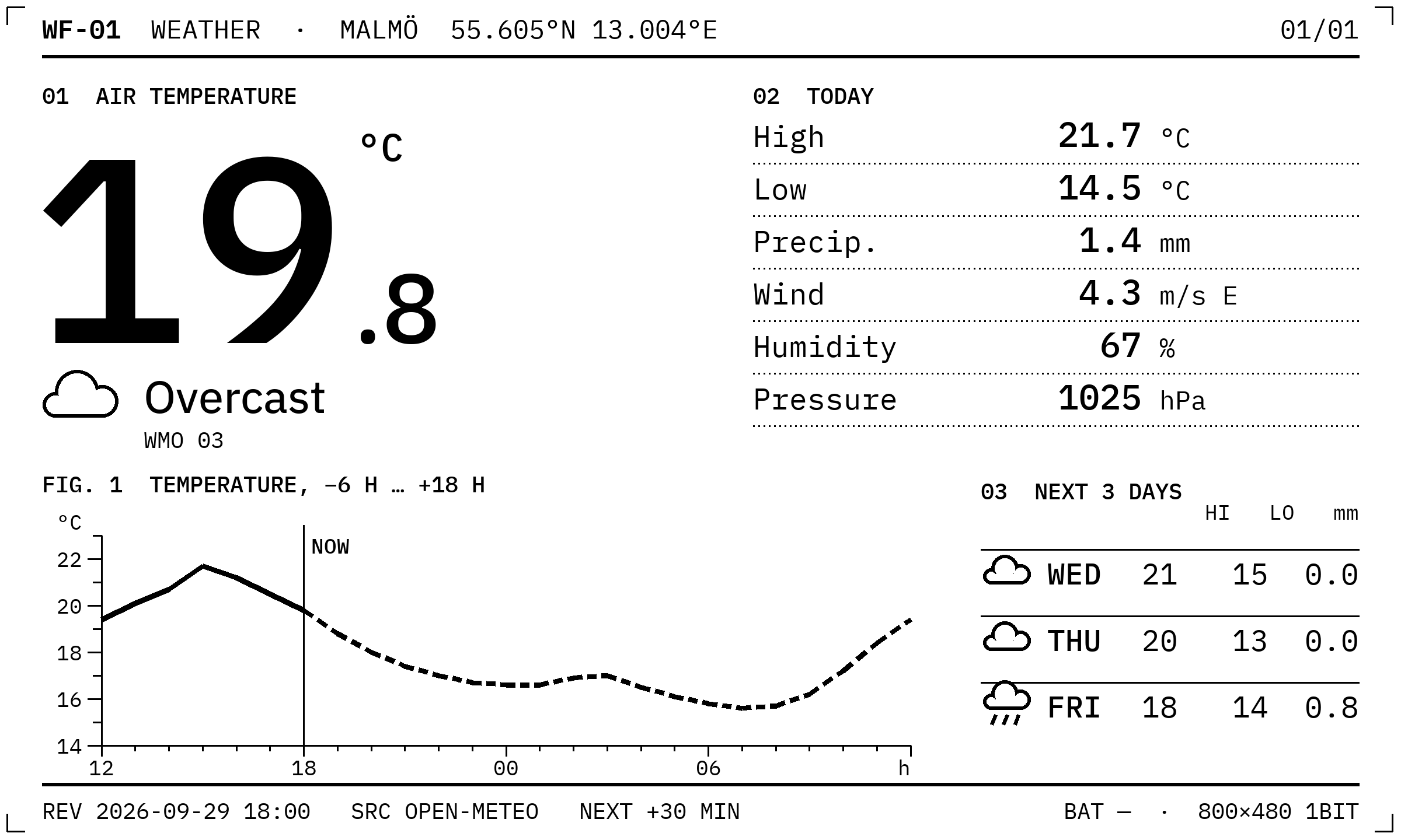
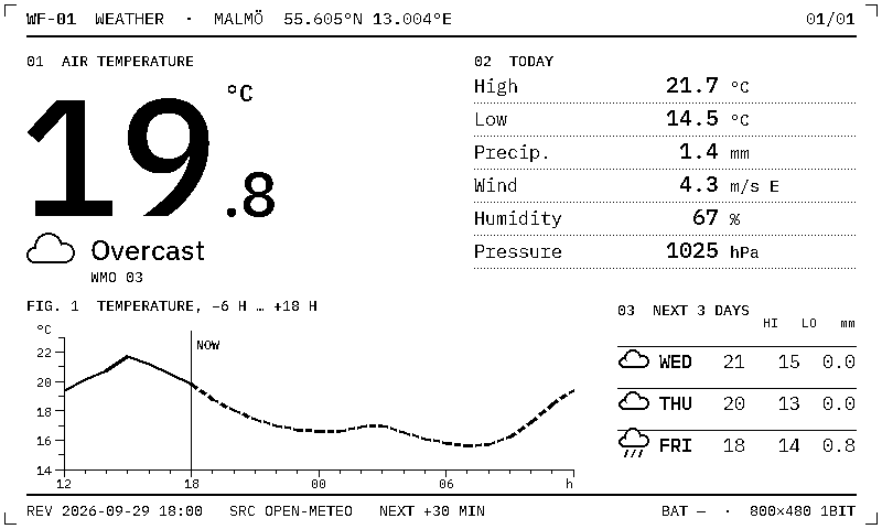
The screen follows the same datasheet layout as this document. Every value carries a label and a unit.
| Area | Content |
|---|---|
| Header | Part number, location, coordinates, sheet index |
| 01 Air temperature | Current temperature (the largest element on the screen), condition icon and name, WMO weather code |
| 02 Today | High, low (°C), precipitation (mm), wind (m/s and direction), humidity (%), pressure (hPa) |
| FIG. 1 Temperature | Curve from −6 h to +18 h. Solid line: measured. Dashed line: forecast. Vertical line: now |
| 03 Next 3 days | Day, icon, high, low (°C), precipitation (mm) |
| Footer | Time of the last update, data source, time of the next update, battery, panel format |
The footer shows the image's age. The panel keeps its image with no power, so a frame that has stopped updating still shows when it last updated.
Weather data: Open-Meteo, no account or key. Units: °C, mm, m/s, %, hPa.
05 Operation
Each update runs the same cycle. Any failure ends the cycle early, leaves the panel unchanged and returns the frame to sleep.
| Step | Action | Limit |
|---|---|---|
| 1 | Wake from deep sleep on the RTC timer | 30 min interval |
| 2 | Connect to the configured Wi-Fi network | 20 s timeout |
| 3 | Request the image over HTTP | 15 s read timeout |
| 4 | Check the image is exactly 48 000 bytes | reject otherwise |
| 5 | Power the panel and draw a full refresh | 2.4–2.8 s measured |
| 6 | Switch Wi-Fi off and enter deep sleep | 100 µA typ. |
The host renders a new image on its own schedule. The frame always shows the most recent image the host served.
06 Specifications
Display
| Parameter | Value | Unit |
|---|---|---|
| Panel | GDEQ0426T82 | |
| Diagonal | 4.26 | in |
| Resolution | 800 × 480 | px |
| Colour depth | 1 | bit |
| Pixel density | 8.62 (219) | px/mm (ppi) |
| Active area | 92.8 × 55.68 | mm |
| Panel outline | 105.33 × 62.37 × 0.93 | mm |
| Full refresh | 2.4–2.8 (panel datasheet: 1.5) | s |
| Partial refresh | 0.42 | s |
| Image retention, unpowered | indefinite |
Controller
| Parameter | Value | Unit |
|---|---|---|
| Module | Adafruit Feather ESP32-S3 | |
| Processor | ESP32-S3, dual-core Xtensa LX7 | |
| Clock | 240 | MHz |
| SRAM | 512 | KB |
| Flash | 8 | MB |
| PSRAM | none | |
| Wireless | 802.11 b/g/n, 2.4 GHz | |
| Bluetooth | LE 5 | |
| Frame buffer | 48 | KB, in SRAM |
| Fuel gauge | MAX17048 | |
| Expansion | STEMMA QT (I²C) |
Power
| Parameter | Min | Typ | Max | Unit |
|---|---|---|---|---|
| Battery, LiPo nominal | 3.7 | V | ||
| Battery capacity | 1500 | mAh | ||
| Usable capacity | 1200 | mAh | ||
| Sleep current | 100 | µA | ||
| Charge per update | 0.15 | mAh | ||
| Charge input, USB-C | 5 | V |
Battery protection: built-in PCM. Connector: JST-PH 2-pin.
07 Battery life
Y: runtime, months · X: update intervalEstimate
Show the numbers
| Update every | Days | Months |
|---|---|---|
| 5 min | 26 | 0.9 |
| 15 min | 71 | 2.3 |
| 30 min | 125 | 4.1 |
| 1 h | 200 | 6.6 |
| 6 h | 400 | 13.2 |
| 1 day | 471 | 15.5 |
Runtime = usable capacity ÷ (sleep charge per day + charge per update × updates per day). Values are typical for the figures in section 06 at room temperature. The on-board fuel gauge reports the real state of charge.
08 Image format
| Property | Value |
|---|---|
| Size | 800 × 480 px, exactly 48 000 bytes |
| Order | Row-major, 100 bytes per row, top row first |
| Bit order | Most significant bit = leftmost pixel |
| Polarity | 1 = black, 0 = white |
| Transport | HTTP GET from the host |
Photographs are dithered (Floyd–Steinberg) before they are sent. Text and lines are drawn pure black and white.
09 Assembly
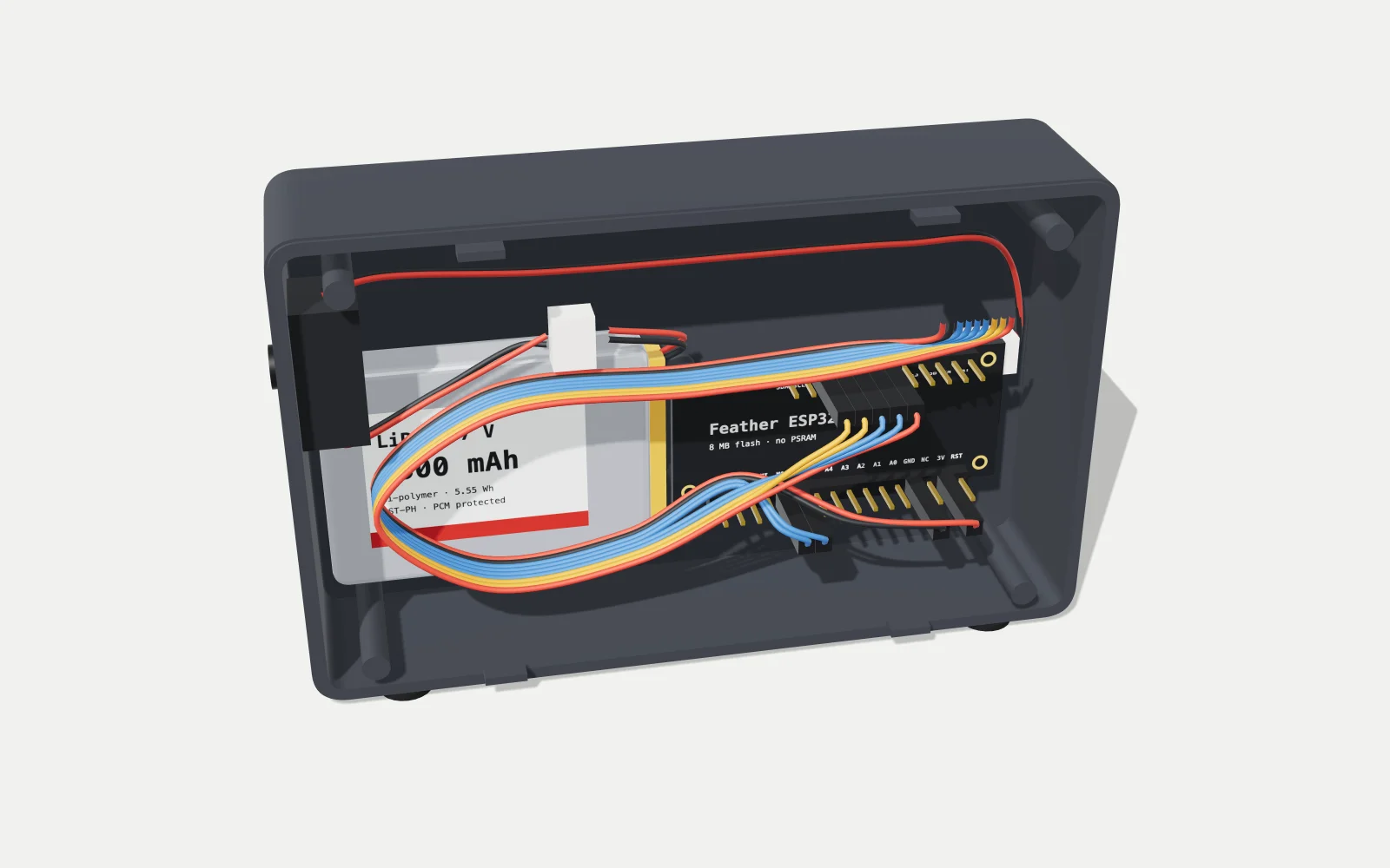
The frame is six layers, stacked from back to front: shell, power switch, battery, controller with its cable, display driver board with the panel, and bezel. Select Exploded in FIG. 1 to see them apart, or Inside to see the shell with the display removed.
| Step | Action |
|---|---|
| 1 | Solder the controller's headers, long pins pointing down. The strips sit in a breadboard while the 28 joints are soldered, so they stay straight. |
| 2 | Test on the bench on USB power only. The ribbon is latched on the back of the driver board, the GH1.25 end of the cable plugs into the driver board and the nine wire ends push onto the controller pins. With the firmware flashed and the host serving the image, the weather appears. |
| 3 | Add the battery and switch. The battery plugs into the switch cable and the switch cable into the controller, the red wire to + on the controller. With the button pressed and USB unplugged, the screen updates every 30 minutes. |
| 4 | Print the bezel and back shell in PETG or PLA, 0.2 mm layers. Before anything else, the display board must drop into the bezel pocket. |
| 5 | Fit the display. The bezel lies face down on a cloth and the driver board drops in, panel first. The panel is already glued to the board; it is held by the board edges, never by the glass. |
| 6 | Fit the back shell. The controller screws upside down onto its three standoffs, USB-C against the slot. The switch's button pushes out through the left-wall hole. The battery sticks to the back wall with foam tape, and the spare cables coil over it under a cable tie. |
| 7 | Close it up. The shell presses into the bezel until the four tabs click. The four ribs hold the display flat against the window. |
10 Revision history
| Rev | Date | Change |
|---|---|---|
| 0.3 | 2026-10-04 | Full refresh measured on the bench; runtime and mass marked typ. |
| 0.2 | 2026-10-03 | E-Display naming, panel-resolution figure, assembly steps and inside view, controller clock, SRAM and Bluetooth, figure text corrected |
| 0.1 | 2026-09-29 | First release |